Thats a model with SEM ignition then. Runs with direct AC from ur alternator to coil/cdi combination underneath ur tank. Killswitch connects Ur ground to ignition and kills engine.
The part U mentioning is for the 12V DC part.
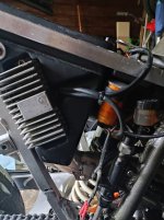
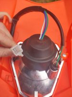
The grey box, the regulator makes about 12V DC. The condensator makes more nicely 12V DC out of it. U need this for indicators, horn, lights. U could attach a simple switch that connect/disconnect ur 12V DC circuit. Or not. 12V while running engine and 0V with engine off.
")
Wiring diagram for old models helps.
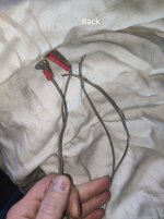
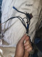
Alternator should have blue and yellow to regulator. Redwhite is + Brown is -. Redwhite to + of condensator, Brown to -. From there u can connect ur devices.
Hallo liebe Leute, ich bräuchte mal eure Hilfe, hätte da zwei Fragen: 1. Meine KTM ist laut Schein das Modell KTM ER LC4 600 EZ. 30.03.1993 a) ist die er lc4 600 dieselbe wie die lc4 600 EGS, denn ich finde leider nichts im netz zu ER LC4 600, sondern nur zu der EGS, besonders beim Schaltplan...
www.ktm-lc4.net